(China (Mainland))

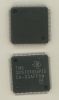
Product Summary
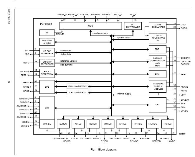
The PCF50604HN/03/2C is a Controller for power supply and battery management. The PCF50604HN/03/2C is a highly integrated solution for power supply generation, battery management including charging and a SIM card interface including supply generation. The device is controlled by a host controller via a 400 kHz I2C-bus serial interface. The application of the PCF50604HN/03/2C is Mobile phones.
Parametrics
PCF50604HN/03/2C absolute maximum ratings: (1)VBAT main battery input voltage: 0 to 5.7V; (2)VSAVE backup battery input voltage: 0 to 5.7V; (3)VCHG charger input voltage DC: 0 to 15.0V; (4)VCHGMIN minimum charger voltage enabling MBC module: 2.7V; (5)fCLKCCO high clock frequency 32 kHz clock available: 3.42 to 3.78 MHz.
Features
PCF50604HN/03/2C features: (1)Serial 400 kHz I2C-bus interface to transfer the control data between the PCF50603 and the host controller; (2)On/Off Control (OOC) module to control the power ramp-up and ramp-down sequences for the handset. Furthermore it determines the supported system operating states: NOPOWER, SAVE, STANDBY and ACTIVE to realize minimum power consumption in all states; (3)Internal Current Controlled Oscillator (CCO) generates the internal high clock frequency. The generated frequency is typically 3.6 MHz; (4)An accurate 32.768 kHz oscillator. This oscillator can be used to supply the 32 kHz clock domains in the system, to improve the accuracy of the internal clock and to reduce the power consumption of the PCF50603; (5)Interrupt controller (INT) that generates the interrupt request for the host controller. All interrupt sources can be masked.; (6)The Real Time Clock (RTC) module uses the 32 kHz clock to provide time reference and alarm functions with wake up control for the handset; (7)One accessory recognition pin with debounce filters and capability to start up the system (REC1_N); (8)One accessory detection comparator input pin with programmable threshold levels that issues an interrupt when an accessory is connected (REC2_N); (9)Two Pulse-Width Modulators (PWM1 and PWM2) which generate an output voltage with programmable duty cycle and frequency; (10)Two LED modulators (LED1 and LED2) capable of generating eight different blinking patterns with eight different repetition periods; (11)Three General Purpose Outputs (GPO) programmable via the serial interface. The GPOs are open-drain NMOST outputs, capable of handling the full battery voltage range and high sink currents. The GPOs can be programmed to be continuously active LOW or 3-state, in addition the GPO outputs can be controlled by the LED or PWM modulators; (12)Watchdog timer that can be activated by softwa.
Diagrams
 |
 PCF5001 |
Other |
|
Data Sheet |
Negotiable |
|
||||||
|
PCF50603 |
Other |
|
Data Sheet |
Negotiable |
|
||||||
|
PCF50613HN023UM |
|
IC PMU CC/CV USIM 52HVQFN |
Data Sheet |
|
|
||||||
|
PCF50617HN032UM |
|
IC PMU CC/CV USIM 52HVQFN |
Data Sheet |
|
|
||||||
|
PCF50622HN042UM |
|
IC PMU CC/CV USIM 52HVQFN |
Data Sheet |
|
|
||||||
|
PCF50622HN2042UM |
|
IC PMU CC/CV USIM 52HVQFN |
Data Sheet |
|
|
||||||